
For each technical object (a system or spatial element: see here for an introduction), it is possible to formulate requirements on the detail view. The detail view features a number of tables where you can fill in/select different kinds of requirements. Below we will go through each of the tables.
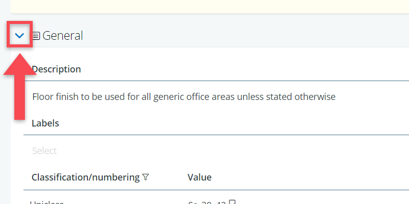
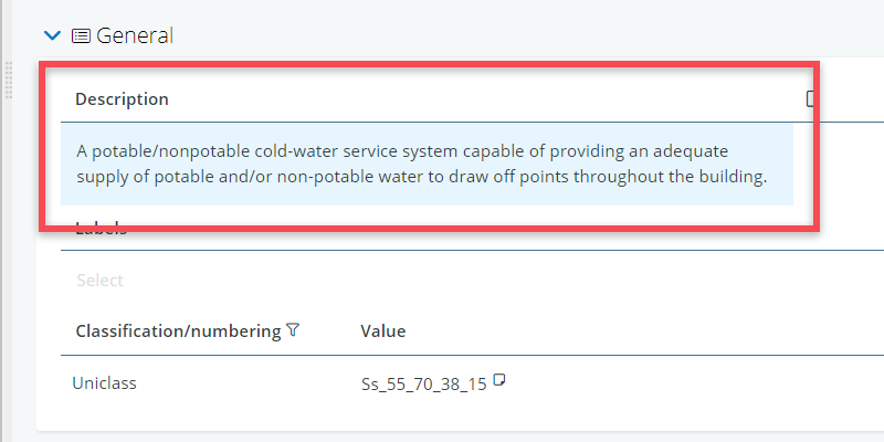
Description
This is the place to enter a general description of a system or spatial element, explaining its general purpose or function.
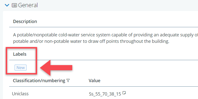
Labels
Labels are not requirements, but rather tags or categorizations that you can add to objects. You can create them but just starting to type in the label field.
For example, in a renovation project, you may wish to label systems as existing or new.
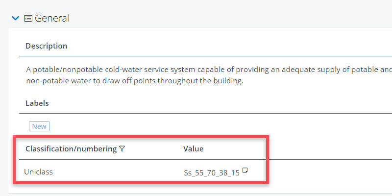
Classifications/numbering
Classifications and numberings can be used to identify and categorize the systems and elements in your model, e.g. a classification according to Uniclass, OmniClass, CCS or SfB.
(Optional) standard properties
Standard properties can be defined via the standard properties settings and they apply to all objects of the same type in that tree (in this case all elements or all systems). Relevant properties may be characteristics such as warranty or technical condition.
However, because of diversity of objects in the systems and elements tree (e.g. ranging from water taps and office partitions to CCTV systems and PV-panels), the usefulness of standard properties tends to be limited.
More relevant are optional standard properties. Optional standard properties are like normal standard properties, but they can be linked (as a block) to specific objects.
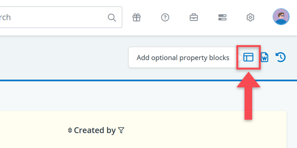
Optional standard property blocks can be linked to an object’s detail view via the icon in the upper right corner of the detail view.
Custom properties
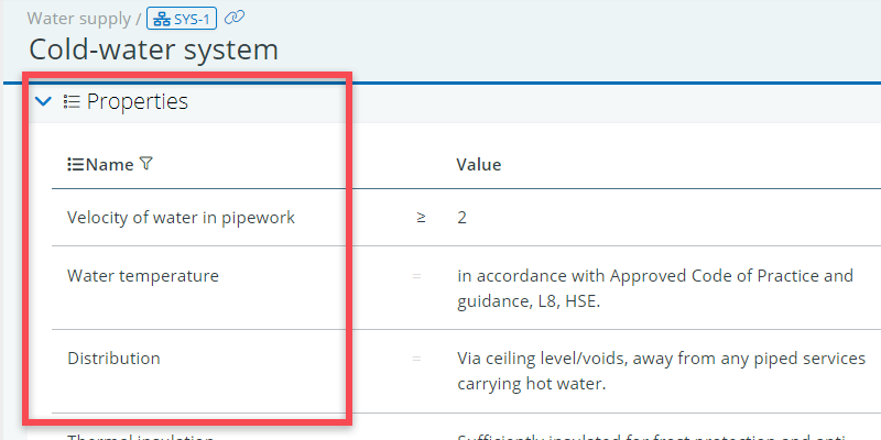
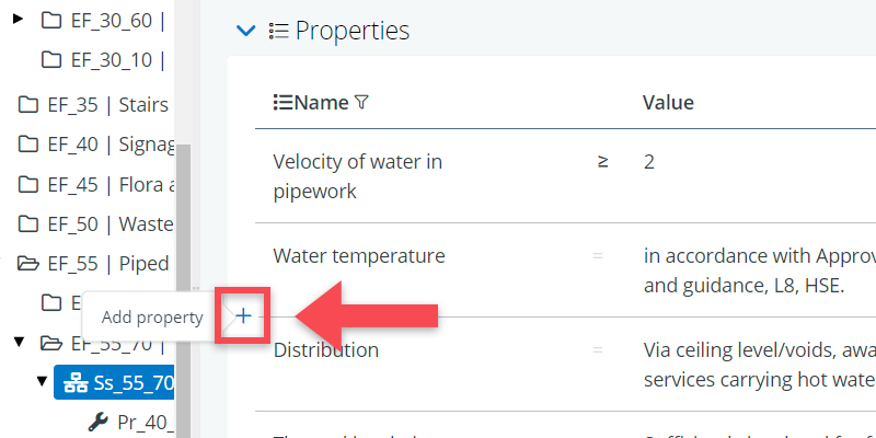
The table Properties is the spot where you add custom properties concerning the system’s or element’s qualities.
Properties can cover anything from performance, capacity, flexibility, material or warranty periods. Below there is an example of the properties of a cold-water service system.
Placement
The table Placement allows you to link systems and elements to the spatial break down structure, indicating where they need to be placed. In this it is important to note the following:
- Systems can be linked the building or civil structure as whole, or to space groups.
- Spatial elements can be linked to specific spaces (buildings) or specific segments (infrastructure projects)
The reason for this difference is that systems are overall functions (e.g. a HVAC system), with lots of parts, that cannot be linked to a particular space. In contrast, spatial elements are tangible, typically countable items (e.g. a power socket) that have a distinct location in a room or space.
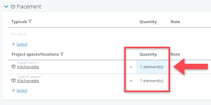
To link a system or element, you have to click Select, you will be able to choose locations to add from the space tree.
In the case of spatial elements, you can also add a quantity to the location relation.
Interfaces
The interfaces with other systems / elements table allows you to define an interface relationship or link between one system or element and another.
In a building project, you may for example want to specify that the CCTV system should be connected to the building management system (BMS) or the UPS system.
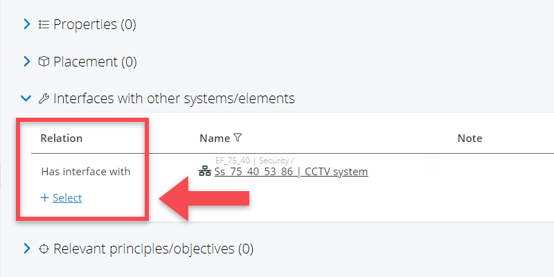
Once you click on Select, you will be able to choose systems or elements to link to from the systems & elements tree. You can add notes if necessary to further specify or explain the requested interface.
You can also access a visual representation of the interfaces you have defined for your project by using the interfaces diagram or by making a cross table (which will give you an interface matrix)
Uploads
The last table on the detail page is the one for Uploads. This table will allow you to upload files you feel are relevant for this particular system or element.
Uploads can be things like cable diagrams to installation guidelines or specific parts of a standard. Be careful, however, not to ‘hide’ any requirements in these files.
Once you click Upload File, you will be able to choose from any file on the device you are currently on. Upload the file of your choice and add notes if necessary (e.g. reference to a particular page or chapter).