As explained here, the core content in BriefBuilder is presented by way of trees and detail views. Here, we will explain briefly what a detail view is and what kinds of information you can find on it.
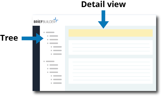
As the name suggests, the detail view is the part of the screen that shows all the detail information of an object. You can see this information when you click on the object in the tree.
Information on the detail view
There are a number of things you can do and see on a detail view.
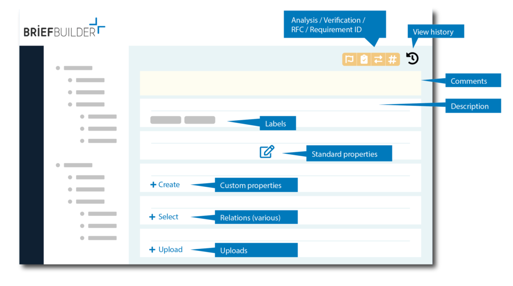
See below for short explanations of each functionality.
Comments
At the top of each detail page you will find the comments table. This is where you or other team members can add comments (e.g. questions or suggestions for improvement) about the information on this page for this specific object. It is a way to facilitate dialogue within the project.
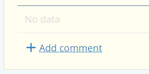
For more info about how to make comments, respond to them, and find them, see here.
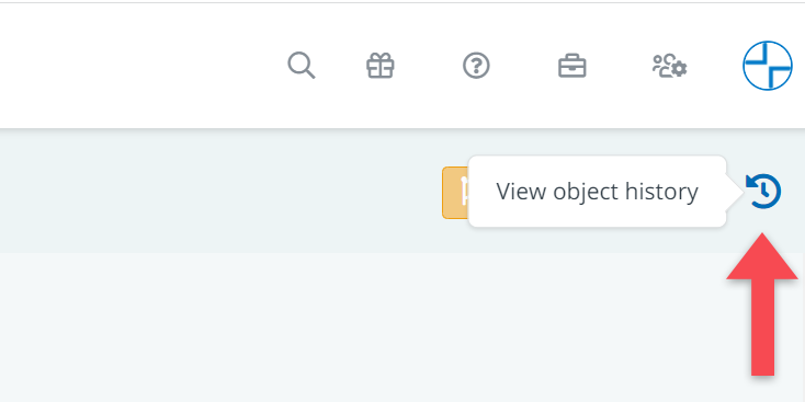
View object history
If you want to know what has happened to the object – in terms of modifications, deletions or additions – you can click on the button in the upper right corner of the object.
View analysis data
If you click on the first of the four view buttons in the upper right corner of the detail view, you can toggle on the available analysis data. This view button is represented by a small flag.
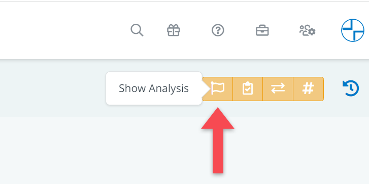
Typically, analysis data concerns notes from the design/engineering team about the feasibility or clarity of requirements. The feature can also be used to assign responsibilities (who is responsible for which requirements?).
Click here for more information about requirements analysis.
View risk data
The second of the four view buttons in the viewing options toolbar is the Show risk button. With this toggle users can view the risks linked to requirements on an object detail page. These appear as a lightning icon. A grey icon means no risk is linked; a black icon with a red badge indicates one or more risks are assigned.
Learn more in our article explaining the risk module.

View verification data
Clicking on the second of the four view buttons extends your view with verification information concerning the requirements that you see on the detail view. This view button is represented by a check mark.
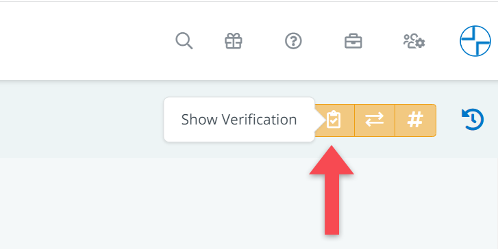
When doing so, you get to see the verification plan (how to verify whether a requirement has been met) and the verification result (outcome and possible link to a demonstration document)
Click here for more information about verification.
View request for change (RFC) data
Toggling on the third of the view buttons extends your view with the available data on requests for change (RFC) made for any of the requirements that you see on the detail view. This button is represented by two horizontal arrows.
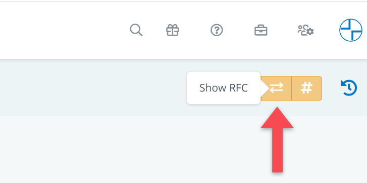
This data allows you to see whether any of the requirements on your detail view has been subject to change. RFCs show detailed information about a change, including possible whys and hows, and what the requirement looked like before it was subject to a request for change.
Click here for more information about RFCs.
View requirement IDs
If you click on the last of the four view buttons in the upper right corner of the detail view, you can choose to extend your view with requirement IDs. This view button is represented by a number sign (#).
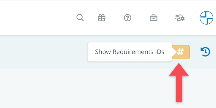
These are automatically generated numbers that you can use to identify individual requirements (e.g. in comments, documents or meetings).
Add a description
In the table General, it is possible to add a description to an object. This will not always be necessary, but it is a good place to describe the general purpose and nature of the object.
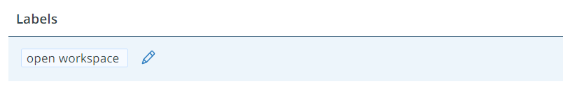
Add labels
Also in the table General , you can add a label or ‘tag’ to an object. The purpose of adding labels is generally to categorize objects to make it easier to find them in trees and tabular overview (e.g. you may want to be able to easily find all spaces that are labelled as ‘open work space’ when defining requirements for acoustic comfort)
To create or add a label, just start typing. When you do so, you will get suggestions based on labels that have been used for other objects.
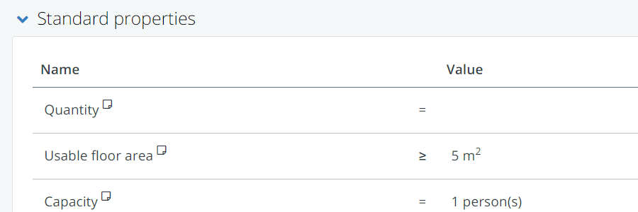
Add values for standard properties
Standard properties are the properties that are shown for each and every object of a particular type. For the object type ‘spaces’ for example, a standard property may be ‘usable floor area’.
On the detail view, you can just click on the value field to enter the value.
You can define the standard properties in the requirement settings menu. See here for a short video about how you can do that.
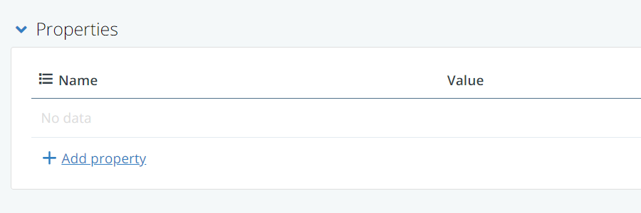
Add custom properties
In addition to the standard properties, you may want to add custom properties for a specific element. This is often the case for technical systems which may have very different properties for different systems.
To add custom properties, click on the Add property button. If you do so, you will be able to fill in a name and a value.
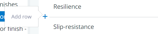
If you already have a list of properties, you can also insert a property between two existing ones. To do this, click on the icon that appears when you hover with your mouse near the starting point of one the table’s separation lines.
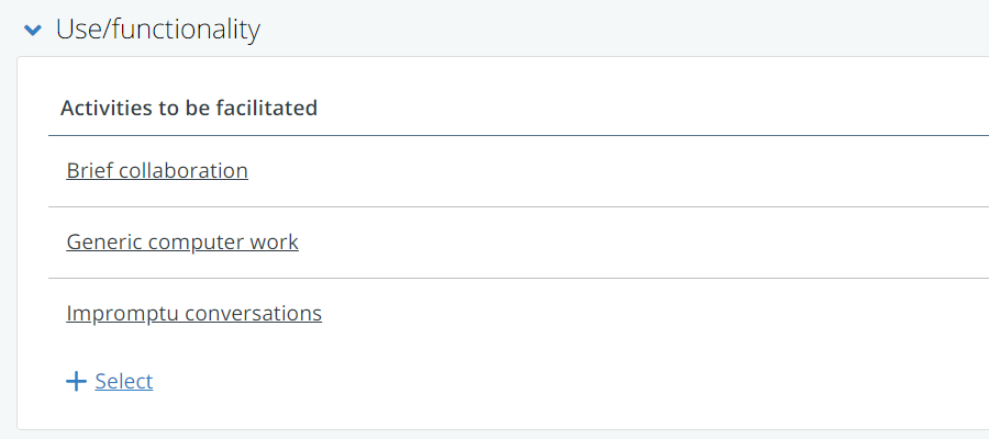
Make relations to other objects
In most detail views, there wil be various tables in which you make links/relations to objects from other trees.
You may, for example, want create a relation from a space (e.g. open plan workstation) to a technical element (e.g. powersocket) or to a user activity (e.g. computer work).
To do so, simply click on the Select button. Depending on the type of relation, it may be possible to add a quantity or a distance to the relation.
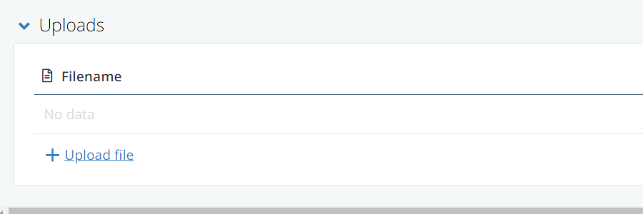
Upload documents
The Uploads table at the very bottom of the detail view allows you to upload files, as additional information for an object. Think of sketches, photos or other kinds of documentation that can help the design/engineering team with understanding the requirements for the object in question.
To upload a file, simply click on the Upload file button.