
The spatial parts of your project can be defined and specified in the tree Spaces & locations.
In building projects, this tree is usually the most important part of the model as spaces tend to carry most of the project’s requirements. Basically, it is a room book with room data sheets.
In infrastructure projects, this tree tends to be used for defining the locational and geometrical aspects of the project (e.g., road segments, traffic lanes, cable corridors and their positions).
In the tree, you can create the following object types:
Building-related:
Building
Group of spaces
Space
Outdoor space
Infrastructure-related:
Location
Connection
Segment
Civil structure
You can obviously also mix building and infrastructure objects. See further down in this article for definitions and constraints for each of the objects.
Good to know: for the objects space, outdoor space, and segment, you can create so-called typicals. Typicals are standardized ‘building blocks’ for reocurring objects that should all have the same requirements, such as classrooms in schools, patient rooms in hospitals or road segments in infrastructure projects.
Below, we’ll explain more about this.
Typical objects and project objects
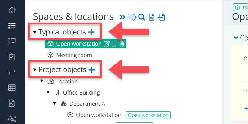
When opening the Spaces & locations tree, you will notice that it is a bit different from the other trees in BriefBuilder. It is divided into two parts:
- Typical objects: this is where you can define the key ‘building blocks’ for your project.
- Project objects: this is where you can make your project decomposition.
Typical objects
A typical object is a standardized (outdoor) space or segment that you can use as a building block for your project decomposition.
Typicals are a very practical thing to have for objects that are frequently occurring in your project decomposition and that should have, more or less, the same requirements.
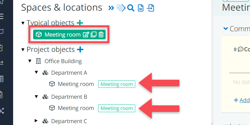
For example: in an office building project, you may want to create meeting room as a typical as you are likely to use it multiple times: department A will need meeting rooms, and so will departments B and C, etc. In that case, it is practical to have a typical called meeting room, with a standardized set of requirements, that you can use again and again. See the image below.
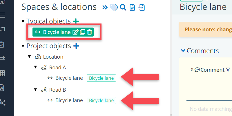
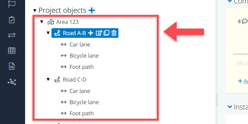
The same goes for an infrastructure project. When defining the requirements for multiple roads, it is likely these should have the same kind of segments, e.g., bicycle lanes, which should all have the same set of requirements. In that case, you will want to create a typical called bicycle lane, which you can then use and re-use throughout your decomposition.
Project objects
Project objects are the actual spatial objects that you ask for in your project. Think of a building, at a particular location, with so and so many spaces of a particular kind. Or, in an infrastructure project, a road or rail connection between A and B, with so and so many traffic lanes.
The list of project objects that you ask for in your construction project, is what we refer to as a spatial project decomposition or a tree structure.
To create a project decomposition, you start with a top object (e.g., building or location), which you then ‘decompose’, step-by-step, into smaller parts. These parts become more concrete, more detailed and more ‘material’ as you work you way down the decomposition structure.
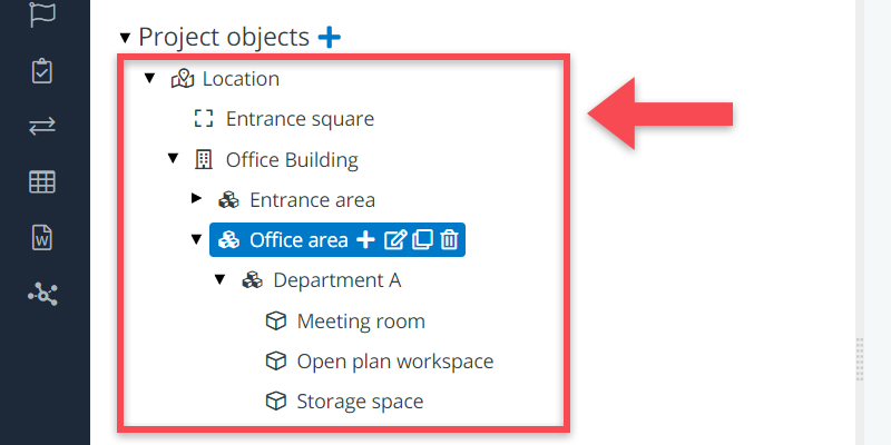
For a building project, the decomposition tree tends to be built up as follows:
- You often start with a location or a building object as the top object of your tree.
- Next, there are likely to be one or two levels of groups of spaces , which can be used to cluster spaces of a particular kind (e.g., meeting spaces) or to cluster spaces for a particular user (e.g., department A or B).
- And at the lowest level, there will be spaces with all the specific requirements thereof.
- Outdoor spaces are often located on the same level as the building, unless this concerns outdoor spaces that are part of the building (e.g., roof terrace).
For an infrastructure project (e.g., a road, a rail link or tunnel), your decomposition will look somewhat different, using different object types. It may be structured like this:
- You probably start with a location object as the top object, indicating the area where the connection has to be realized and/or to indicate the actual locations that have to be connected.
- Next, there is the connection itself, which may be subdivided into a smaller parts and/or be linked to other connections (e.g., an existing road).
- At the lowest level of the connection’s spatial subdivision will be specific segments, which typically carry concrete geometric requirements such as width or length, and can have relations to spatial elements such as traffic lights or road markings.
- Civil structures may be added to indicate the location or geometry of building-like entities such as pump stations or water reservoirs.
Creating spatial objects
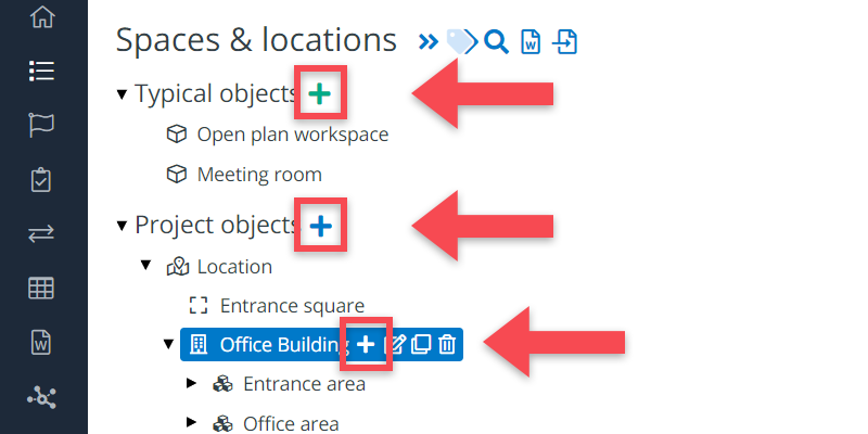
In both the Typical Objects tree and the Project Objects tree, you can easily create objects by clicking on the icon at the top of the page, or the icon behind the name of the object under which you want to position your object.
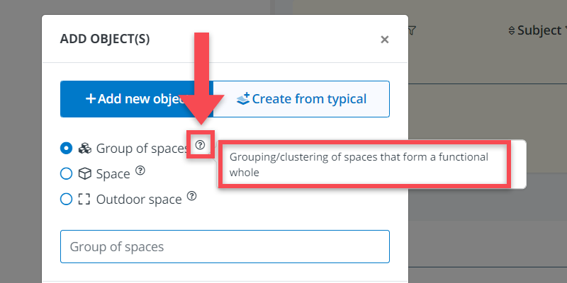
A window will pop up offering you the options to choose from (as discussed above). Click on one of the options and provide a name for the object.
Note that you cannot just create any object type at any position in the tree.
You can, for example, not create a building as an object under a space because spaces are a part of the building—not the other way round. Nor can you create a space under a space because that would lead to confusion in the calculation of the project’s total size.
See below for a more detailed explanation of the different object types and their constraints concerning the placing of other objects underneath them (so-called child-objects or sub-objects).
Definitions of the types of objects
Location
This object represents the specific site, address or plot where a building or infrastructural object is located or must be realised. The object can be used to capture, for example, zoning requirements.
Possible sub-objects: all other objects
Connection
This objects represents an infrastructural connection between two points. This can be a high-level object such as a road connection or rail track between two locations, but also a very specific connection such as a cable corridor or a street.
Possible sub-objects: connection, segment, civil structure
Segment
A segment is a specific functional or spatial part of an connection. E.g., a traffic lane or tunnel segment. Typically segments have a concrete width or length.
Possible sub-objects: none (this is to allow for the integration with BIM models in relation to the placement of spatial elements such as traffic lights, street furniture etc.)
Civil structure
This object is the spatial and/or functional representation of a built structure other than a building. E.g., a pump station, offshore platform or water treatment facility. Just like a building (see below) it can be further subdivided into spaces and groups of spaces.
Possible sub-objects: segment, group of spaces, space, outdoor space
Building
A building represents a structure that provides shelter for occupants or contents and stands at a specific location. This object can be used as a starting point for a breakdown of all the spaces that should be located in the same building.
Possible sub-objects: group of spaces, space, outdoor space
Group of Spaces
This object can be used to indicate larger areas or parts of a building which can then be broken down or subdivided into individual spaces. Examples of grouping areas include departments in hospitals, the entrance area of a public building or a conference center at a campus.
Possible sub-objects: group of spaces, space, outdoor space
Spaces
This object is the most basic unit of the project’s space tree. They are the actual volumes where user activities take place. Spaces are often the most important objects of the model as they carry most of the requirements. They can have a size, capacity, particular room items, acoustic qualities, and so on.
Possible sub-objects: none (this is to allow for the integration with BIM models in relation to the placement of spatial elements such as fittings, furniture, etc.)
Outdoor Spaces
This object is essentially the same as the regular spaces above, but specifically labelled as being outdoors. Examples of outdoor spaces are parking spaces, playgrounds, and bicycle storage.
Possible sub-objects: none (this is to allow for the integration with BIM models in relation to the placement of spatial elements such out door lighting elements, outdoor furniture, etc.)