
The user equipment module in BriefBuilder can be used to define and manage the specific kinds of equipment that will be placed in a facility and used by its end users. This includes items such as medical imaging systems in hospitals, laboratory devices in research centers, or interactive displays in educational environments.
These equipment items are often not part of the project’s scope, but the presence of these items drives the requirements of a space (e.g. number of power outlets, floor load capacity, door width, etc.), so it is crucial design information. For instance, a CT scanner may require shielding to reduce radiation, a data center rack may demand increased floor load capacity and a teaching room’s smart board may ask for extra wall sockets.
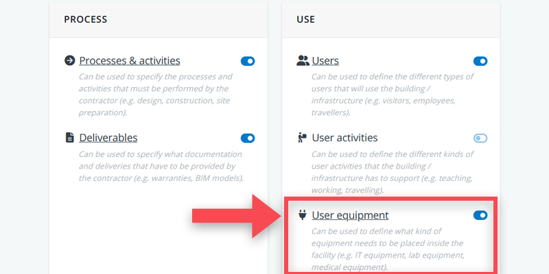
Activating the user equipment module
The user equipment tree in BriefBuilder is a module that is not active by default when starting a new project. To activate it, you have to go to the modules part of the settings menu (as explained in this article).
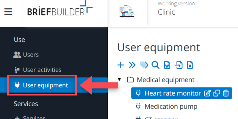
With the module active you can navigate to the user equipment tree, located under requirements > use > user equipment in the navigation menu on the left.
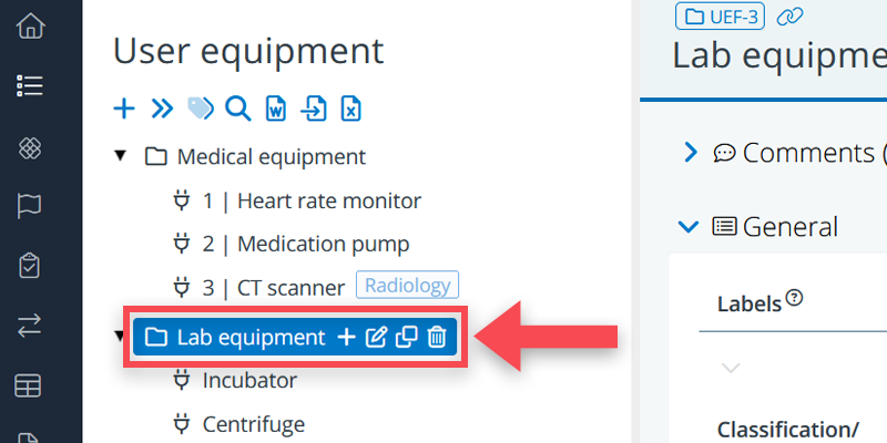
Defining user equipment objects
In the equipment tree, you can define two kinds of objects: user equipment and folders.
The user equipment objects represent the actual equipment items (or equipment types), and the folders can be used to organize your tree structure. You may, for example, want to group your equipment items according to their functionality, distinguishing between IT-equipment, medical equipment, lab, equipment and so on.
Working with user equipment
To define and explain user equipment items, you can use:
- Descriptions
- Labels
- Classifications / numbering
- Properties
- Relations with spaces
- Relations with other user equipment
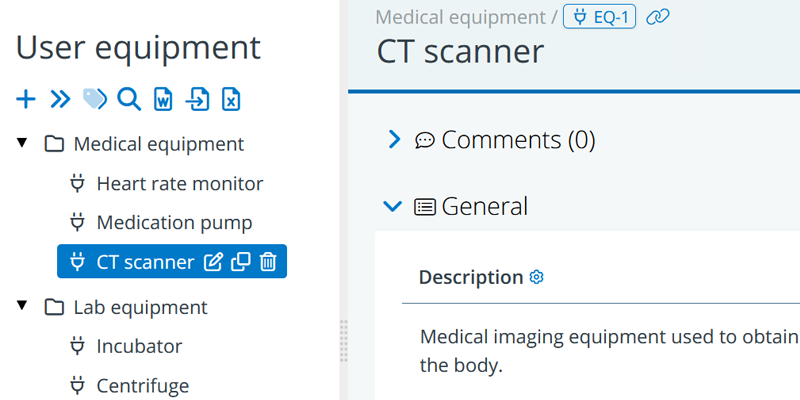
Descriptions
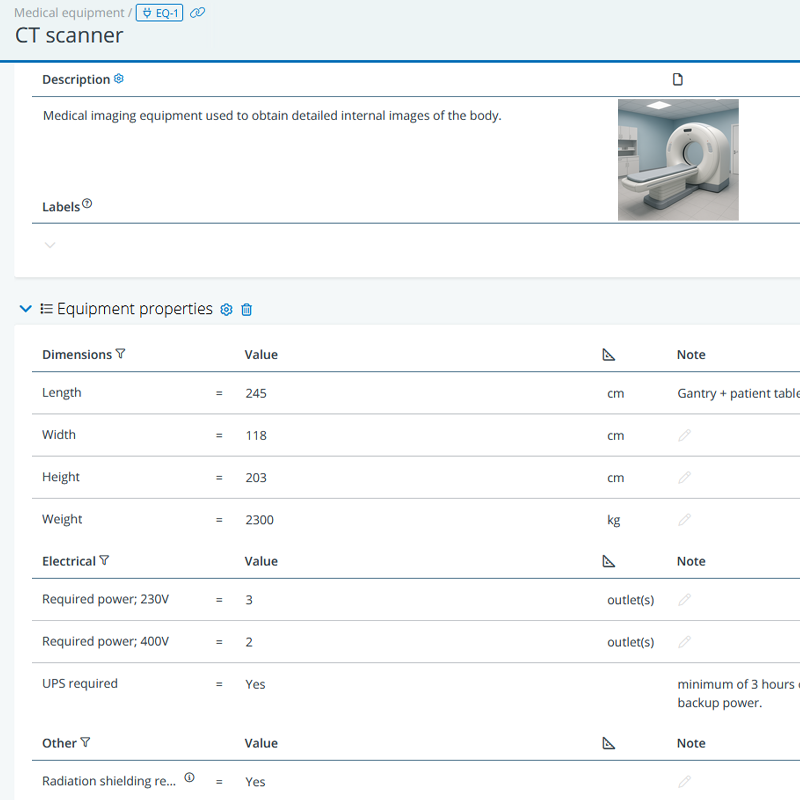
Descriptions can be used for a short textual explanation of what kind of equipment it is. In the example above, the field is used to give a bit more explanation about what a CT scanner is.
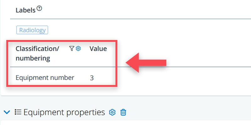
Classifications / numbering
It is also possible to add particular number of ID to an equipment piece. This is of particular relevance in case it concerns existing equipment. In that case, equipment items may have a particular ERP number or even a QR-code.
This information can be captured in the classification/numbering part of the data sheets. More explanation here.
Properties
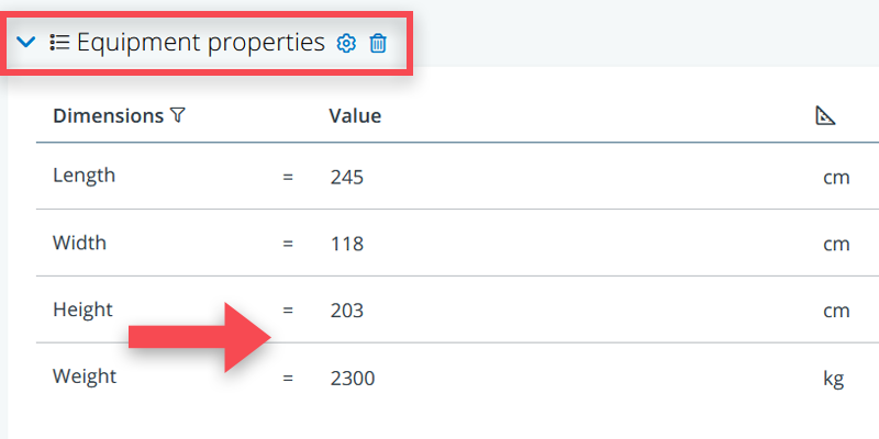
Most important in describing the equipment items are, typically, their properties. Think of properties such as power need (relevant to define the number of power outlets in a room), weight (relevant for floor loads), dimensions (relevant for room heights and the size of door openings), sound production (relevant for sound insulation) and other specifics.
To help with consistency, it is best to use standard properties and optional property blocks for this purpose.
See here for more info on how to define standard properties.
The benefit of using standard properties is that you can easily create Excel like overviews of all equipment objects and their properties. See here for more about cross tables.
Relations to spaces
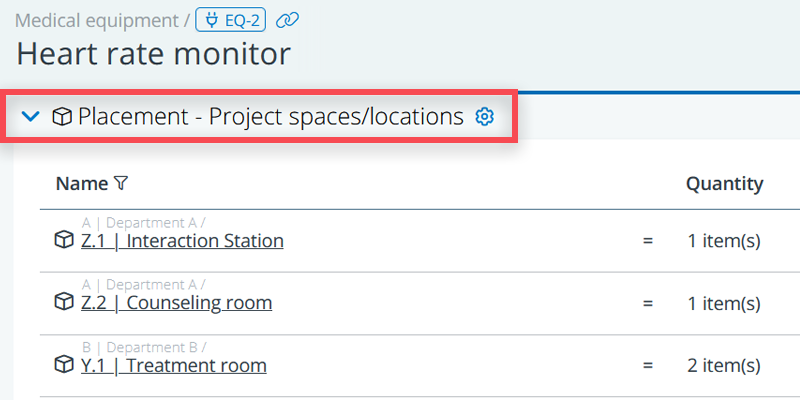
When you have defined your equipment, you can create relations with the spaces where they need to be placed. It allows for a clear overview of what is expected to be placed where. Creating these relations ensures that requirements driven by equipment are captured.
For example, a medical pump can be linked to a treatment room, or a projector may be linked to a lecture hall. These relations allow users to:
- Give insight into equipment distribution across a project.
- Identify spatial requirements for specific types of equipment.
Cross checking equipment properties and room requirements
As mentioned in the introduction, equipment properties will drive particular requirements. A classic example: the number of power sockets in a room should be in line with the power need of the equipment in that room (or to be even more precise: with the power need of the equipment that can/should be simultaneously in use in the room).
To validate whether that is the case, it is best to make use of cross tables, and in particular the possibility to add a ‘combined tree(part)’.
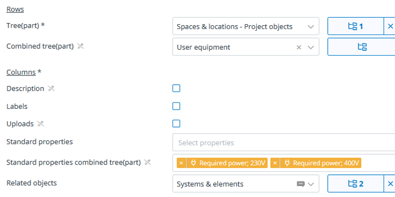
For the example above, you would make the following selections:
Tree: Spaces
Combined tree: User equipment
Standard properties of the combined tree: Required power; 230V + Required power; 400V, in this case.
Related objects: Systems & elements, and then select the power sockets.
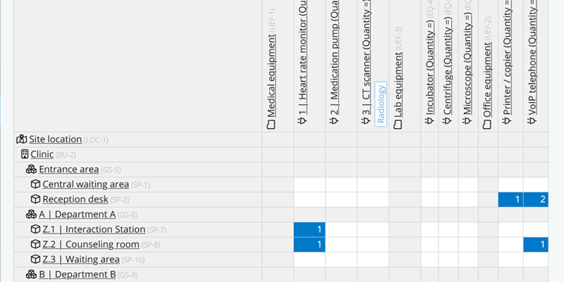
This selection results in the following cross table:

This overview doesn’t calculate whether you have under- or over specified the number of power sockets, but it gives the electrical engineer a clear overview of what is asked for and what has been specified. For example: the cross table indicates that there are two equipment items in the CT Imaging Suite: a heart rate monitor that requires two 230V power outlets. And a CT scanner that requires four 230V power outlets. Which is in line with the specified number of power sockets for that space (the dark blue cells in this case).