BriefBuilder has a dedicated IFC module that allows you to import an IFC file into your model. Below, you can watch the promotional video to get a general understanding of what you can do with it.
In this article, we’ll dive into the details of this new feature. You can read about:
- Activating the IFC module
- The background and purpose of the feature
- Importing IFC files into BriefBuilder
- Viewing IFC data in BriefBuilder
Click on the topics above to jump straight to the part that you are interested in!
Activating the IFC module
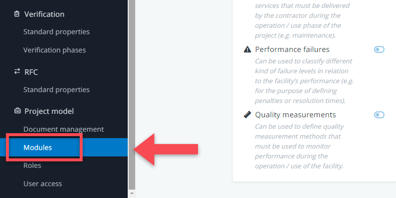
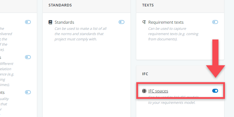
To activate the IFC module, you need to go to the settings menu and click on modules. In the module overview, you will find the IFC module in the lower right corner.
Background and Purpose
The IFC module enables you to import IFC data into BriefBuilder and automatically connect the ‘required spaces’ (defined in BriefBuilder) to the ‘designed spaces’ (specified in the IFC file). This integration provides a direct insight into how requirements are translated into spatial design solutions.
The primary objective of this integration is to bridge the gap between briefing and design, and to link requirements to design solutions.
As a construction client, you can use this feature to quickly determine where your spaces have ‘ended up’ within the design. As a design team, you can use the integration to conduct checks to see how floor plans align with the client’s requirements.
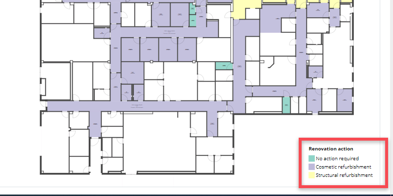
In the case of renovation projects, you may want to use this feature to link requirements to existing building plans. For instance, you can define which spaces need to be fully renovated and which ones simply need a fresh coat of paint. See example below.
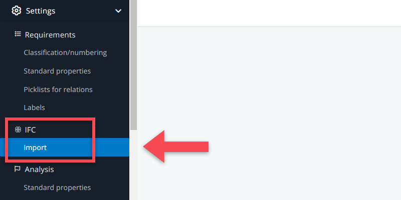
Importing IFC files
IFC files can be imported via BriefBuilder’s settings menu.
The import process consists of 4 steps:
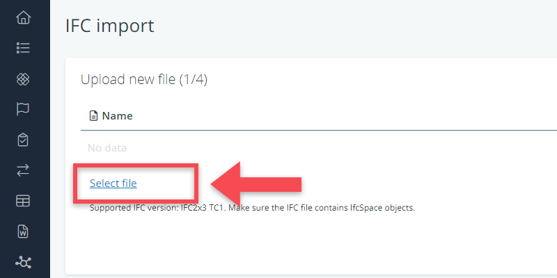
Step 1: Select file
Select the IFC file that you want to import into BriefBuilder. Make sure that the file contains spaces (IfcSpace) and that the format is IFC2x3 TC1.
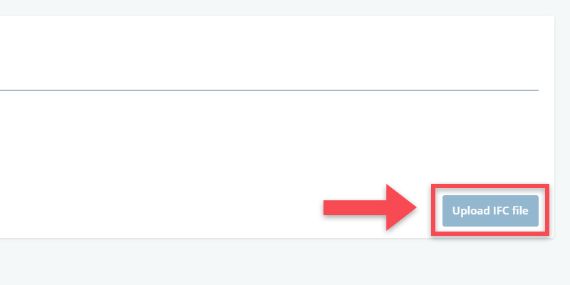
Step 2: Upload file
Once you have selected a file, click on upload IFC file on the right hand side of your screen. BriefBuilder will then process the file. The processing time may vary depending on the size and complexity of the IFC model.
Step 3: Define mapping rule
In this step, you can define the mapping rule that automatically maps the IFC spaces to the spaces defined in BriefBuilder.
For both the BriefBuilder spaces and the IFC spaces, you need to select which attribute should be used for the mapping process.
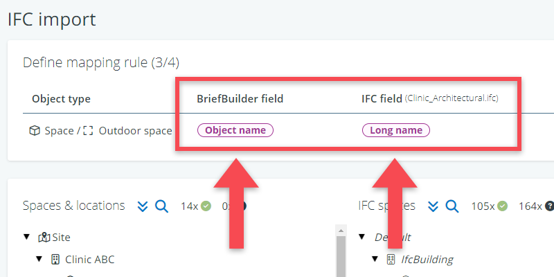
The mapping process can be performed in various ways. One common approach is to match the IFC long name with the object name in BriefBuilder. However, the mapping can also be based on BriefBuilder’s object IDs and the IDs on the IFC side, provided they are similar. The specific approach depends on the BIM protocol agreed upon for the project.
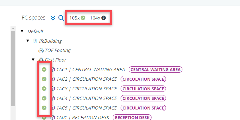
As you select these attributes, you will immediately see how the mapping works in the tree view below. Checkmarks and question marks indicate whether a space is mapped or not.
Step 4: Import IFC tree
Once you are satisfied with the mapping, click on the Import IFC tree button in the lower right corner to initiate the actual import of the IFC information into the BriefBuilder model.
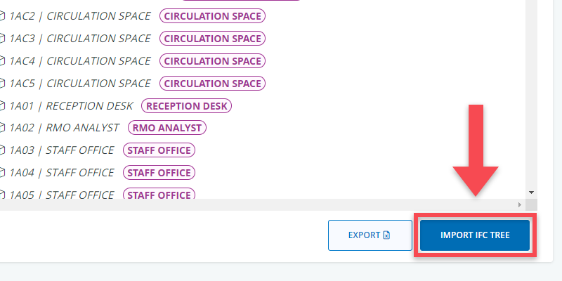
The duration of the import process depends on the size and complexity of the IFC file.
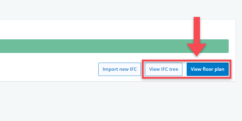
Once the import process is complete, you can access the IFC data by clicking on either View IFC tree or View floor plan.
Viewing IFC data
IFC data that has been imported into BriefBuilder can be viewed and approached from different directions. Below we’ll explain the different possibilities in detail.
On the detail view of a BriefBuilder space
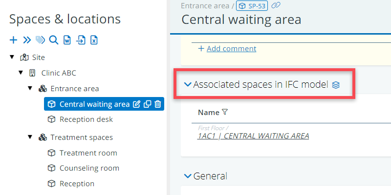
On the detail of a BriefBuilder space, you can see the mapped IFC spaces in the table Associated spaces IFC model.
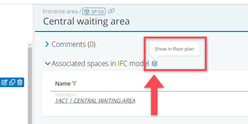
There, you can also see a icon which brings you to the floor plan viewer where the relevant spaces will be highlighted in blue.
IFC tree
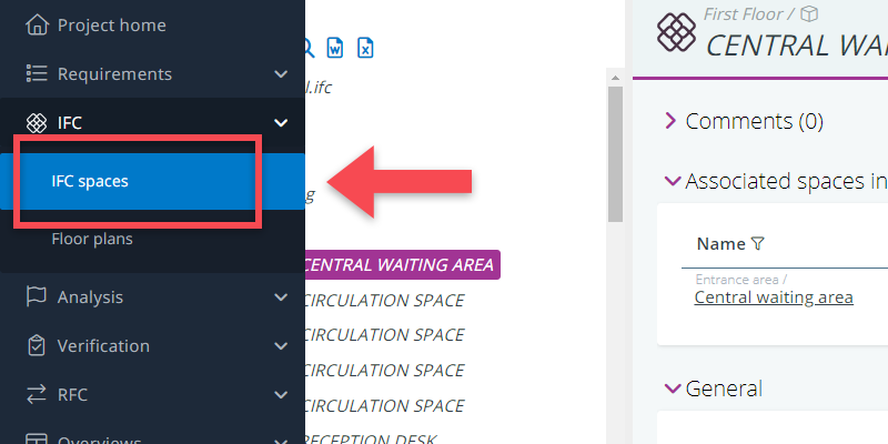
In the navigation menu, under the IFC header, you can find the menu item IFC Spaces. If you click on that, you will find all the IFC spaces presented in a tree structure.
For each IFC space, you can see the details by clicking on them in the tree, just like you do in any other BriefBuilder tree.
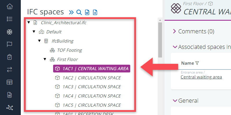
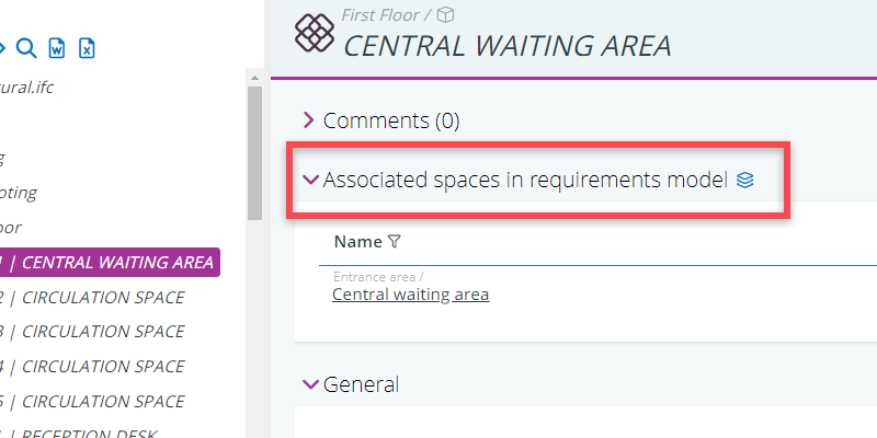
To see which BriefBuilder space an IFC space is connected to, you have to go to the table Associated spaces in requirements model.
Floor plan viewer
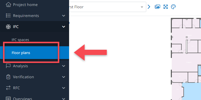
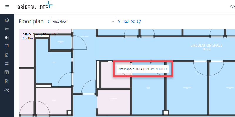
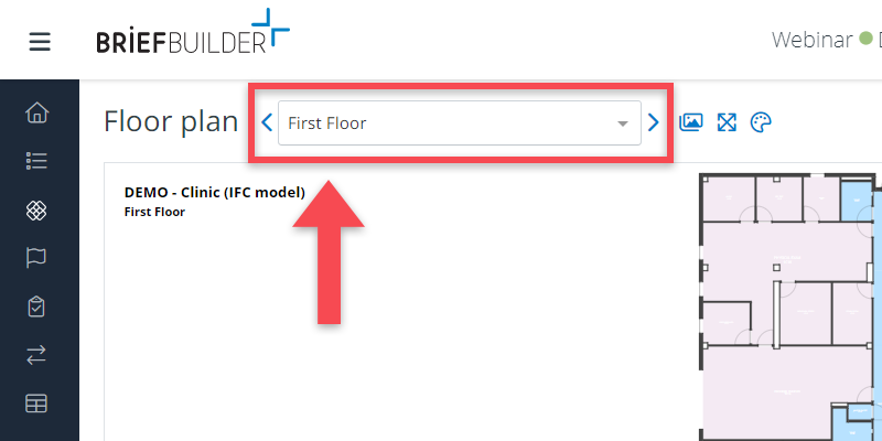
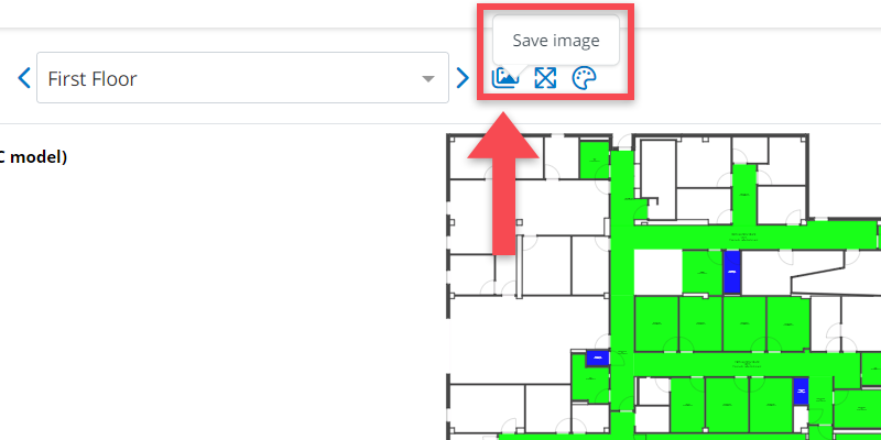
In the navigation menu, you will also see the menu item Floor plans. This will bring you to a 2D viewer of the IFC data.
In the viewer, you can view the different floor levels of the building and the spaces that are placed on those floors as well as the walls, windows and doors (if present in provided IFC file).
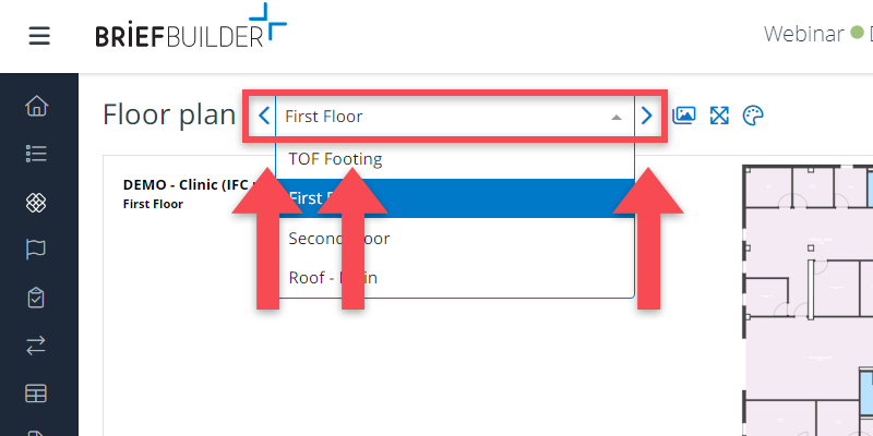
To navigate through the different floor levels, you can either use the pull down menu or click on the small icons on either side of it.
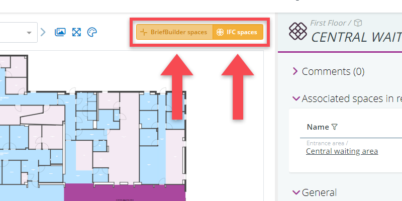
When clicking on a space in a floor plan, you can choose to see either the IFC data or the associated BriefBuilder data by using the yellow buttons.
Heat maps
In the floor plan viewer (Navigation menu > IFC > Floor plans), it is also possible create ‘heatmaps’ in which requirements data or IFC data are projected onto floor plans by means of colour schemes.
Such heatmaps can help visualize how requirements have been translated into the building’s spatial design, which can be useful for the communication with the building’s users and for analysing both the requirements and the design proposal.
You can create two kinds of heatmaps:
- a heatmap that shows the values of a single property (e.g. temperature level)
- a heatmap that shows the ratio between the values of two properties (e.g. the ratio between the spaces’ sizes in the BriefBuilder model and in the IFC model).
Heatmap for single property
Step 1: Go to the floor that you want to look at
Step 2: Click on the palette icon ()
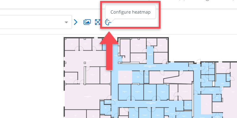
Step 3: Select the property you want to see in your heatap
When clicking on the icon, you will get a pop-up with several selections:
- To see one property, select View a single object property
- Next, select whether you want to see a requirement property (as captured in BriefBuilder) or an IFC property (as captured in the IFC file)
- Finally, select the specific property that you want to see (e.g. temperature level, security zoning etc., dependent on how your model has been set up)
Once you have made the data selection, choose the color scheme you want to use. Note: for properties with picklists as input type (e.g. class A, B and C), you can choose a set of discrete colors. For other properties (e.g. size), you will only be able to to choose a continuous color scale.
When you’re happy with your selections, click on apply.
Heatmap for a ratio of two properties
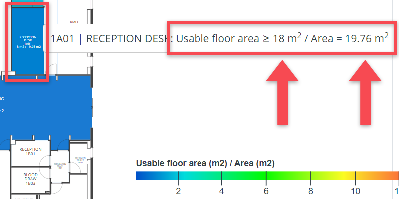
For properties with numerical values, it is possible to show the ratio between the values of two properties.
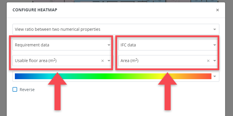
Basically, you do the same as explained above, but select you have to select View ratio between two numerical properties.
This can, for example, be relevant when you want to check the sizes of spaces between the IFC model and the BriefBuilder model. In that case, you select Usable floor area as requirement, and Area as IFC data. The floorplan will then show the ratio between these two values. A space with a ratio lower than 1 is larger than what is asked for. A ratio that is higher than 1 means that the space is smaller.
IFC data in cross tables
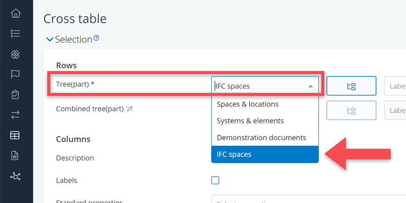
IFC data can also been viewed in Excel-like cross tables. For this, you have to go the cross tables in the navigation bar (can be found under the header overviews).
In the selections menu, you should select IFC Spaces as the tree that should be shown as rows.
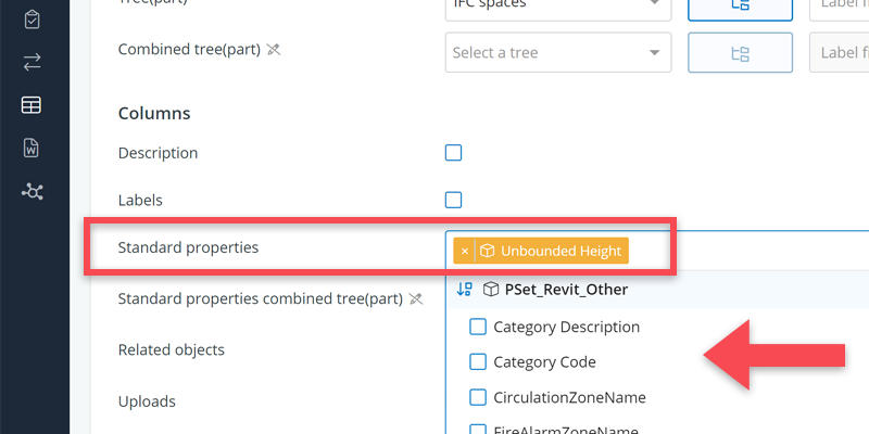
Next, you should select the IFC properties that you want to see in the columns.
Once you are happy with your selections, click on Show.
Combining IFC and requirements data in cross tables
It is also possible to show both IFC and requirements data in a single cross table. This can be useful for if you want to make comparisons.
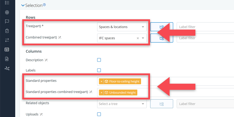
To do so, it is usually best to select Spaces & locations are your prime tree, and then add the IFC spaces as the combined tree.
And then select for both trees which properties you want to see.
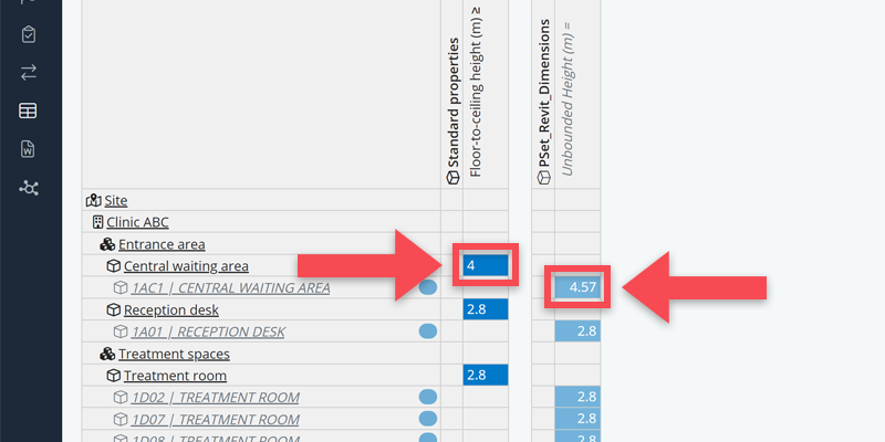
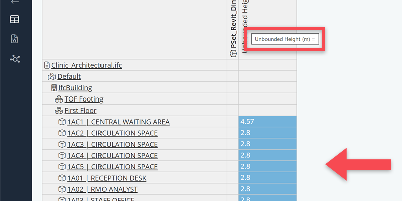
In the example below, we have chosen the spaces’ free height for both, called floor-to-ceiling height in BriefBuilder and Unbounded height in this particular IFC model.
In the resulting cross table, you first see a BriefBuilder space and its required height, then all the corresponding IFC spaces with their specific heights. From the overview, you can easily deduct where the IFC model is deviating from the what has been asked for.